(520)780-9751
 | ||||||
 | ||||||
 | ||||||
 | ||||||
Saw Cut Loops
Preformed Saw-Cut Inductance Loops
Direct Burial Loops
PR-3/16
Vehicle Detection Inductance Loops
Saw Cut or Direct Burial
Over 34 standard sizes; 200 of each model always in stock. Custom loop dimensions or lead-in length are always available and can be shipped same day.
Loop is packaged as a kit. Everything you need is inside the package and will save 15-30min in installation time per loop.
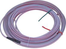
Preformed Direct Burial Inductance Loops
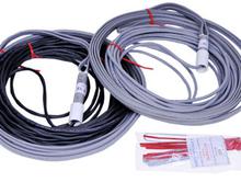
Preformed Saw-Cut Loop Installation Kit
Inductance Loops – How they Work
The first step to installing a worry-free access control system is understanding not just the operator, but all the accessories too! Loops, that copper wire in the ground is one of the most misunderstood pieces of any access control system. Understanding the fundamental basics of loops will allow a quick and easy installation without call-backs. Here is your guide to how inductance loops work.
When direct current passes through a wire an Electric Magnetic Field or Flux (EMF) is created around the wire. An example is when a wire is coiled around a metal rod then energized with a battery; current flows through the wire and causes the rod to act like a magnet. The more turns in the coil or increases in current flow the greater the magnetic field or pull.
If the current is removed, the magnet field collapses back into the wire. In the case of Alternating Current such as AC, the current changes direction and sets up a magnetic field opposite of the same when the current was passing in the opposite direction. In an AC circuit, the field that is collapsing is pushing against the new developing field. This “pushing back” is a form of resistance known as Inductance. Anytime you have AC passing through a wire you will have this special resistance of Inductance. All detection loops will have AC current applied to them. That is why detection loops are referred to as Inductance loops. This inductance is measured in units of Henrys. A common range of inductance for a detection loop is 40 to 300 micro Henrys.
When a detector energizes a loop with an AC current; the size of the loop, number of winding in the loop, length of lead-in wire and wire size will determine the total resistance or inductance of the loop circuit. The detector will determine how much current is flowing through the loop and set that amount as the standard. When a metal object enters the EMF field created by the loop current, the metal object absorbs some of the collapsing EMF fields. Because some of the collapsing EMF field is now absorbed, it lowers the resistance in the loop circuit. This causes an increase in current flow through the wire that is detected by the detector. When this happens, the detector will either open or close a relay switch that activates a command in the gate operator such as open for exit, reverse for safety, or hold open or close for a swing gate with a center or shadow function.
Loop phasing comes into play when two loops are used with the same detector. A common application would be when two reverse loops are used with one on each side of a sliding or vertical gate. Proper phasing is accomplished when the loops are connected in series with each loop current flowing in the same clockwise or counter clockwise direction.oop phasing comes into play when two loops are used with the same detector. A common application would be when two reverse loops are used with one on each side of a sliding or vertical gate. Proper phasing is accomplished when the loops are connected in series with each loop current flowing in the same clockwise or counter clockwise direction.
With the current flowing in the same direction in each loop, you will notice that the two loop legs nearest the gate will have currents moving in the opposite directions. This will cause what is referred to as a “Field Cancellation Effect”. That is, the fields of sensitivity will both have the same magnetic polarity (North or South) toward each other. Since like fields repel, the fields of sensitivity are pushed up and away from each other, causing a dead or null field between the loops. This null or Cancellation effect will allow the loops to be placed closer to the gate without being detected. Because the fields are pushed up, they now are more sensitive next to the gate path, making for a safer reversing loop feature.
On the other hand, if the loops are connected with the current flowing in the opposite directions, the poles of each loop will have an opposite polarity, causing the fields to attract to each other. This will cause what is referred to as a “Field Enhancement Effect”. This will cause the area between the two loops (the gate path) to attract to each other. This effect will increase the sensitivity in the zone where the gate travels, increasing the chance of the gate being detected as it closes. If detected, the reverse detector will keep reversing the operator as the gate tries to close, setting up the requirement to send out a service technician. By arming yourself with this knowledge you will have less repeat service calls and happier customers.
IIf you try to take advantage of loop phasing and discover that the loops are detecting the gate – it may mean that the loops were not properly phased. Don’t worry, you don’t need to pull up the loops and re-install them. You just need to take one lead-in and flip it over. Doing this will change the direction that current flows through the loop and cause the polarity of the loop to change. Hook the loops back up to your detector and see if the gate is still being detected.f you try to take advantage of loop phasing and discover that the loops are detecting the gate – it may mean that the loops were not properly phased. Don’t worry, you don’t need to pull up the loops and re-install them. You just need to take one lead-in and flip it over. Doing this will change the direction that current flows through the loop and cause the polarity of the loop to change. Hook the loops back up to your detector and see if the gate is still being detected.
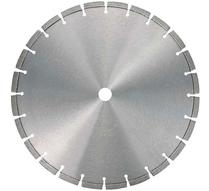
3/16" Pro Diamond Blades
Alabama · Alaska · Arizona · Arkansas · California · Colorado · Connecticut · Delaware · Florida · Georgia · Hawaii · Idaho · Illinois · Indiana · Iowa · Kansas · Kentucky · Louisiana · Maine · Maryland · Massachusetts · Michigan · Minnesota · Mississippi · Missouri · Montana · Nebraska · Nevada · New Hampshire · New Jersey · New Mexico · New York · North Carolina · North Dakota · Ohio · Oklahoma · Oregon · Pennsylvania · Rhode Island · South Carolina · South Dakota · Tennessee · Texas · Utah · Vermont · Virginia · Washington · West Virginia · Wisconsin · Wyoming
SAW CUT LOOP TIPS:
To install a saw-cut loop, a groove must be cut. Choosing the correct size saw-blade is important to insure there is enough space for sealant to properly flow when applied. A 1/8” blade cuts a groove too narrow for thick sealant to properly flow and encapsulate the saw-cut wires. A 3/16” blade or larger has enough space for sealant to flow. BD Loops recommends the use of a 3/16” saw blade, 3/16” blades cost less, put less bog on your saw-cut machine, and require 25% less loop sealant to fill than a ¼” groove. If the sealant doesn’t flow properly air pockets will form within the saw-cut groove, a leading cause in loop failures.
There are a lot of methods used to clean and dry a saw-cut groove, some better than others. Cleaning and drying a groove of water and debris is very important if you want to install a loop properly according to industry standards. If a loop is installed in a groove that is wet and filled with debris the wire has a high chance of becoming nicked, and loop sealant will not harden properly or air bubbles may form. The use of a tool that centralizes air flow like the BD Loops groove cleaning air wand or similar tool is the best way to clean out and quickly dry a saw-cut groove Sucking up water and debris with a shop vacuum or using a leaf blower to dry the groove takes more time, but is more efficient that letting the sun air dry the groove.
Once the loop is in place a loop sealant should be applied. The use of a DOT approved loop sealant like Chemque, Bondo, or Ruscoe brand loop sealant will save a lot of time in installation and prevent early replacement. These brands have a low viscosity, don’t crack over time, and have tools designed for them to make the installation process much easier. Tools like sealant tips, if the proper tip is used the groove can be sealed from the bottom up allowing a seal with just one pass. Normal methods require multiple passes because time must be given for the thick sealant to flow around the wires. (See Figure 4) BD Loops found that 15-20 minutes per loop can be saved in the sealant application step with the use of a properly sized sealant tip. Loop sealant is often applied with the installer on their hands and knees, save your knees and back by using a rolling work seat Once the loop is in place a loop sealant should be applied. The use of a DOT approved loop sealant like Chemque, Bondo, or Ruscoe brand loop sealant will save a lot of time in installation and prevent early replacement. These brands have a low viscosity, don’t crack over time, and have tools designed for them to make the installation process much easier. Tools like sealant tips, if the proper tip is used the groove can be sealed from the bottom up allowing a seal with just one pass. Normal methods require multiple passes because time must be given for the thick sealant to flow around the wires. BD Loops found that 15-20 minutes per loop can be saved in the sealant application step with the use of a properly sized sealant tip. Loop sealant is often applied with the installer on their hands and knees, save your knees and back by using a rolling work seat
Loop sealants take time to harden you can leave the job quicker and looking nicer by always having some different colored sand on your truck. Colored sand is inexpensive and commonly found at hobby stores. After the groove is filled with sealant sprinkle some sand on top choosing a color that matches the surface material. This will allow the lane to be opened earlier, before the sealant has fully hardened. Applying sand is also a good trick if the only color of loop sealant available is black when installing into a light colored surface such as concrete. By mixing both white and brown sand the color of concrete can be mimicked and better conceal the loop tattoo.oop sealants take time to harden you can leave the job quicker and looking nicer by always having some different colored sand on your truck. Colored sand is inexpensive and commonly found at hobby stores. After the groove is filled with sealant sprinkle some sand on top choosing a color that matches the surface material. This will allow the lane to be opened earlier, before the sealant has fully hardened. Applying sand is also a good trick if the only color of loop sealant available is black when installing into a light colored surface such as concrete. By mixing both white and brown sand the color of concrete can be mimicked and better conceal the loop tattoo.
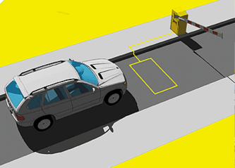
Vehicle detection loops or inductive-loop traffic detectors can detect vehicles. Loops are used to stop or reverse a moving gate, to allow free exit from or entrance to a site, or as an "arming loop" to allow entrance.
Secure Lane LLC Copyright © 2013 Secure Lane LLC, All Rights Reserved | Tucson, AZ USA (520)780-9751 Contact the webmaster at: christine@secure-lane.com
BD Loop Sealant is a tough and durable polyurethane resin sealant designed to encapsulate, protect and insulate inductance loops for door, gate, and parking applications. Effectively seals out moisture and provides exceptional chemical resistance to de-icing salts, antifreeze, gasoline, motor oil, hydraulic brake fluid and other hydrocarbons. BD Loop Sealant remains strong, flexible and resilient in cold weather. It provides superior adhesion to wires and saw cuts in concrete and asphalt. Application does not require mixing or heating. Permits vehicular traffic immediately after application (see BDLoops.com for installation tips) with no need for lane closure. DOT APPROVED by most States.
The ULTRALOOP ULT-PLG loop detector model has our new DETECT-ON-STOP™ or (DOS) feature, which allows detection only when a vehicle has come to a complete stop on the loop. This exclusive feature is unique to EMX and is a major advantage if you want to ignore cross traffic in tight spaces.
The ULT-PLG provides a solid-state output indicating vehicle presence. The second output can be used for presence, loop fault or pulse on entry/pulse on exit. Our latest vehicle detector provides options for automatic sensitivity boost (ASB), delay, fail-safe/fail-secure and infinite and normal (5 min.) presence.Vehicle Loop Detector ULT-PLG
This detector is easy to install and operate. Sensitivity selection is simplified by the ULTRAMETER™. Ten sensitivity settings allow for finer adjustment of the detection level. The four frequency selections help to prevent crosstalk in multi-loop applications.
The ULT-PLG is compatible with a wide variety of gate operators. Please see the Spec Sheet for a detailed list.
Benefits include:
- Ignores cross traffic in tight spaces with DETECT- ON-STOP™ feature
- Low current draw - green product
- Easy to install and setup with the ULTRAMETER™
- Compatible with many gate operators
- Cost effective
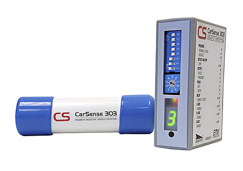
Magnetoresistive Vehicle Detector CarSense 303
The CarSense 303 vehicle detector features advanced 3-axis, magnetoresistive sensing technology that responds to changes in the Earth's magnetic field caused by ferrous objects. Three sensing elements provide measurements in the X, Y and Z axes to improve detection sensitivity when used in either above or below ground installations.
The CS303 is equipped with our new DETECT-ON-STOP™ or (DOS®) feature, which allows detection only when a vehicle has come to a complete stop. This exclusive feature is unique to EMX and is a major advantage if you want to ignore cross traffic in tight spaces.
The detector's compact, loop-less design reduces installation costs when compared to traditional inductive loop technology.
Benefits include:
- Easy installation above or below ground
- Ignores cross traffic in tight spaces with
- DETECT-ON-STOP™ feature
- Quick setup with the ULTRAMETER™
- sensitivity display
- Cost effective
Features
- Three-dimensional presence detection of vehicles
- Select X,Y,Z axis independently
- Stand-alone sensor
- Sensor stores ambient background and settings in non-volatile memory
- Remote control module for programming and additional relay contact output
- ULTRAMETER™ displays optimum sensitivity setting/crosstalk interference
- DETECT-ON-STOP™ allows detection only when a vehicle has come to a complete stop
Vehicle Loop Detectors
BD Loop Shield
(BD-LS) 30 Oz Tubes

